


Busway Design Application and Installation
Release time: 2026-02-02
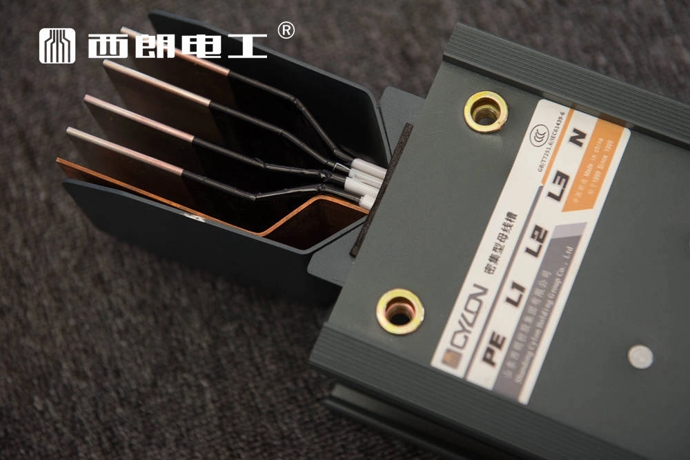
Application of Enclosed Busway in High-Rise Buildings
n high-rise building projects, the architectural discipline typically reserves specific installation spaces (electrical shafts/risers) for enclosed Busway (busbar trunking systems). One or more plug-in tap-off boxes are installed on each floor. Power is then distributed from these tap-off boxes to various electrical equipment and circuits via cables or wires.
Design Considerations
- Redundancy: To ensure the continuity of the power supply, a dual-circuit (double-loop) configuration should be considered, with an adequate safety separation distance maintained between the two circuits wherever possible.
- Capacity Planning: When selecting the specifications for the enclosed busbar, the conductor cross-section should be maximized to ensure sufficient residual capacity (headroom).
- Plug-in Interfaces: While ample plug-in interfaces should be provided, consideration must be given to operation height and the routing of power feeders. If a vertically arranged busbar has too many interfaces, the uppermost tap-off box on each floor may be positioned too high, making operation and maintenance inconvenient.
- Circuit Breaker Selection: Due to the very low line impedance of enclosed busway systems, the circuit breakers selected for the tap-off boxes must have a short-circuit breaking capacity that matches the system requirements.
- Load Calculation (Shear Walls): For enclosed busbars installed vertically on shear walls, it is generally not necessary to provide load data to structural designers. The load data should be calculated using the following formula:
Support Point Load = 0.5 × Floor Height × (Total Weight of Busbar/Total Length of Busbar) - Installation Space: As the structure of an enclosed busbar system is significantly heavier than cable trays, the design must account for adequate hoisting and rigging space.
Precautions for the Application of Busway Systems
- Stability Verification: During design selection, the dynamic stability and thermal stability of the selected model must be verified (calculated) based on the system’s short-circuit current values and the manufacturer’s technical parameters.
- Hazardous Locations: According to current national electrical explosion-proof regulations, enclosed busbar trunking systems are not suitable for Class A or Class B fire/explosion-risk environments. This is primarily because the connection methods at the joints of enclosed busbars do not satisfy explosion-proof requirements.
- Techno-Economic Analysis: Enclosed busbar systems have a high capital cost. For scenarios where loads are concentrated or where equipment requires a dedicated power supply, the use of busbars may not be reasonable from an engineering economic perspective. Additionally, the installation technical requirements—and consequently the installation costs—are higher. Therefore, before deciding to use an enclosed busbar scheme, a comprehensive techno-economic comparison against other solutions must be conducted.
- Maintenance Requirements: While enclosed busway systems are generally considered maintenance-free lines, if they are located in humid environments or areas with corrosive gases (e.g., coastal regions, textile manufacturing plants), comprehensive anti-corrosion coating and maintenance are required every one to two years.